Adjusting Control Valve Selection The size of the two-way control valve is correct when: 1- The control valve, which is fully open at design conditions, achieves the design flow. 2- Maintain sufficient control valve authority, generally higher than 0.25. When the control valve remains fully open for a longer period of time, the first condition needs to be met in order to avoid over-flow and insufficient flow in the other coils. This occurs when the coil is undersized during the start-up night after a nighttime shutdown at night, when the thermostat is set to the lowest cooling condition (which is a common practice), and the control loop is unstable Happening. To obtain design flow at design conditions, the pressure drop in the fully open control valve at design flow must be equal to the locally available pressure difference, ΔH, minus the design pressure drop in the coils and accessories (Figure 3a). Can I use this information when selecting a control valve? We assume that we can. For a 1.6 l / s flow, the control valve available on the market produces a design pressure differential of 13, 30 or 70 kPa without intermediate values. Calculated value generally can not find the corresponding product in the market. Therefore, the control valve is generally large size. Therefore, a counterbalance valve should be installed in order to obtain design flow under design conditions and to improve the characteristics of the control valve without increasing the pressure drop (Figure 3b). After selecting the control valve, we must verify that its valve power ΔpVc / ΔHmax is sufficient. If not enough, the design of the system must be reconsidered in order to be able to create a higher Δp across the smaller control valve. Some Special Designs for Local Problems For some special cases, it is better to work alone than to have the rest of the system react to abnormal conditions. When the selection of the control valve is at a critical state, or when there is a large ΔH variation in the circuit, a local differential pressure controller can be used to stabilize the pressure differential across the valve, as shown in Figure 4a. This is the case of a typical control valve with a minimum valve weight of less than 0.25. The principle is very simple. The diaphragm of the self-operated differential pressure control valve STAP communicates with the inlet and outlet of the temperature control valve. As this pressure differential increases, the force on the diaphragm increases and the STAP is proportionally closed. In this way, the pressure difference on the control valve can actually be kept constant. This pressure differential is selected so that design flow is available at the STAM when the control valve is fully open. Control valve will not be too large size, the valve authority also remained close to one. All extra pressure drops are applied to the STAP. Compared with the temperature control, the pressure control is easier, with a suitable ratio to avoid irregular oscillation. The combination of a local differential pressure controller and a variable speed pump guarantees optimal control conditions, increased comfort, and saves pump energy and reduces noise in the system. For economic reasons, this solution is usually suitable for small systems. For larger systems, ΔH varies widely and a flow rate can be limited by a differential pressure sensor connected to the balance valve (Figure 4b). When the measured pressure differential is consistent with the design flow, the control valve is not allowed to open further. This solution is well suited when the BMS system simultaneously requires that the measured flow rate be around the design value. When the end device is controlled by a switch control valve or a time proportional control valve, the pressure drop limit reduces noise and simplifies the balancing process. In this case, the differential pressure controller can apply a steady pressure differential across a set of end devices, as shown in Figure 5. This solution can also be applied to a small group of devices controlled by a regulating control valve while also increasing its valve authority. These examples are not limiting, but merely show that some special problems can be solved by a specific solution. Heating equipment in the stability of the pressure
Brief Introduction & Working Principle
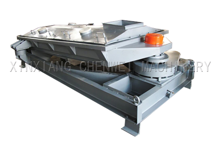
CW series gyratory screen is one of our main products. It`s superior quality, excellent performance and high efficiency won us a good reputation among our customers home and abroad.
The material moving track on screen begin with horizontal circular motion at the feed end, gradually diminishing along the length of the machine to an elliptical path,and finally to an approximate straight line motion at the discharge end. The material have enough time to move on the screen, until the screening process is finished,that is why this machine have huge handling capacity.
The unique gyratory motion imparts a combination of actions to the material as it passes along the screen surface. It begins with a horizontal circular motion at the feed end, gradually diminishing along the length of the machine to an elliptical path, and finally to an approximate straight-line motion at the discharge end. There is no vertical component to this motion thus keeping the material in constant contact with the screen surface. Whole sealing structure, no dust pollution. Without vertical vibration, the mesh could gain a longer service life.
Features
* No vertical vibration when working,longer life span of the screen mesh. (best choice for fragile materials, such as salt, sugar etc. )
* Capacity is about 4 times compared with S49-B series Vibrating Screen
* Low power consumption and high screening efficiency
* Price is much higher compared with S49-B series vibrating screen
* It can be designed in square or linear type
* Self cleaning device available

Gyratory Sifter
Gyratory Sifter,Gyratory Sieving Sifter,Gyratory Vibrating Pellet Sifter,Steel Standard Gyratory Sifter
XINXIANG CHENWEI MACHINERY CO.,LTD , https://www.sieves.nl
