While selecting the right motor for your needs, apart from torque and speed, another key factor to consider is load inertia. Have you ever thought about why racing bikes have wheels and tires that differ from those of mountain bikes? Racing bikes use lighter, thinner wheels to enhance performance. These wheels have lower inertia, making it slightly easier to pedal. In competitive racing, where every millisecond counts, even a small difference can make a big impact.
### What is "Inertia"?
The term "inertia" originates from the Latin word *iners*, meaning idle or sluggish. Inertia is defined as the resistance of any physical object to changes in its velocity. A higher inertia means the object will resist acceleration or deceleration more strongly.
### Understanding Load Inertia
Load inertia, or moment of inertia, refers to the resistance of any physical object to changes in its speed relative to the rotational axis. For a rotating load, it is the product of its mass and the square of the perpendicular distance of the mass from the axis. Load inertia is commonly represented by the letter "J."
### Permissible Load Inertia and Inertia Ratio
Motors cannot handle an unlimited amount of load inertia. Manufacturers often provide guidelines for permissible load inertia or inertia ratios to assist with motor selection. Permissible load inertia values are usually provided for AC and brushless motors (examples are included later in this post). Inertia ratios are typically specified for stepper or servo motors and are calculated by dividing the total load inertia (or reflected load inertia if using a gear system) by the rotor inertia of the motor. Exceeding these values can cause the motor to miss steps, stall, or vibrate. Closed-loop motors generally handle higher inertia ratios compared to open-loop motors.
#### Example: Recommended Inertia Ratios
| **Motor Type** | **Frame Size (mm)** | **Frame Size (NEMA)** | **Inertia Ratio** |
|------------------------------------|---------------------|-----------------------|-------------------|
| Open-Loop Stepper Motors | 20, 28, 35 | 8, 11, 14 | 5:1 or less |
| Open-Loop Stepper Motors | 42, 50, 56.4, 60, 85 | 17, 20, 23, 24, 34 | 10:1 or less |
| Closed-Loop Stepper Motors | - | - | 30:1 or less |
| Servo Motors (Auto Tuning) | - | - | 50:1 or less |
| Servo Motors (Manual Tuning) | - | - | 100:1 or less |
**Tip**: While these guidelines are meant to ensure safety, exceeding them is sometimes possible with the right setup. For instance, I once spoke with someone working on slot machines for casinos. Their team used a stepper motor to spin the reels, determining whether you won or lost. By carefully designing the motion profile, using slow acceleration and deceleration ramps, and conducting extensive testing, they successfully used a motor well beyond the permissible inertia ratio limits.
### How to Calculate Load Inertia?
Let’s explore how to calculate load inertia with some common examples. The fundamental equation for inertia (J) is shown below:
#### Fundamental Inertia (J) Equation
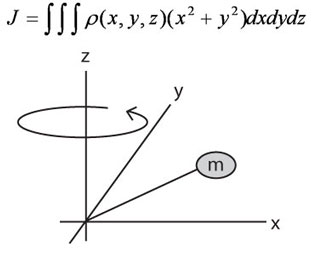
Don’t worry—there are simpler versions of this formula. Below are five simplified equations for calculating inertia of common objects: solid cylinder, hollow cylinder, rectangular object, rectangular object with an off-center axis, and objects in linear motion.
To choose the appropriate equation, consider:
- The shape of the object in motion.
- The rotational axis (X or Y).
- The available details (e.g., weight of the load).
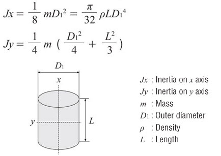
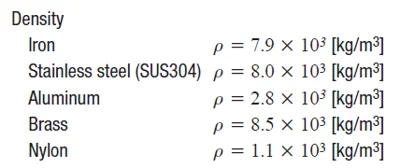
For example, if weight is provided and you’re calculating the inertia of a solid cylinder rotating about its X-axis, use the first equation (Jx) below (with mass “mâ€). If weight isn’t provided but you have the diameter, thickness, and material density, you can calculate inertia with the second equation (Jx) (with density “pâ€).
#### Inertia of a Cylinder or Disc (X or Y Axis)
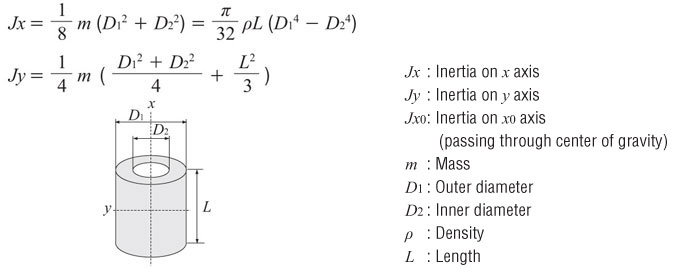
#### Inertia of a Hollow Cylinder (X or Y Axis)
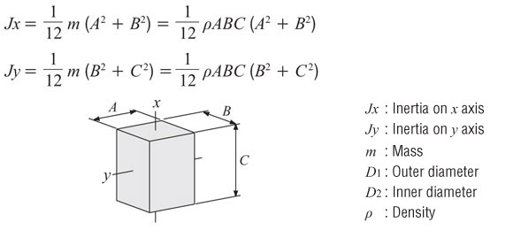
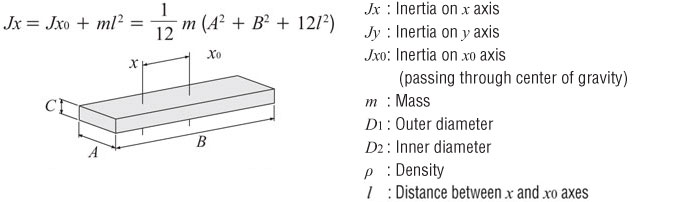
#### Inertia of a Rectangular Object (X or Y Axis)
#### Inertia of a Rectangular Object with Off-Center Axis
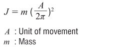
#### Inertia of an Object in Linear Motion
### Units of Measurement
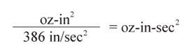
Inertia is commonly expressed in two ways: **oz-in²** and **oz-in-sec²**. The former includes gravity, while the latter focuses solely on mass. Technically, inertia is a function of mass and shouldn’t involve gravity, but measuring mass directly on Earth is impractical.
Oriental Motor typically provides inertia in oz-in². When calculating acceleration torque, we divide the total inertia by gravity:
**Gravity = 386 in/sec²**
- **oz-in²** = Inertia based on weight
- **oz-in-sec²** = Inertia based on mass
#### Conversion from oz-in² to oz-in-sec²
To perform these calculations, additional information such as material density may be required. This helps determine the weight of the object. Further details can be found through a simple online search.
### Example: Load Inertia Calculation
Let’s try calculating the load inertia for the following application. Which components do you need to calculate?
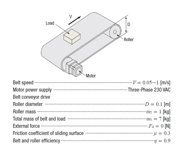
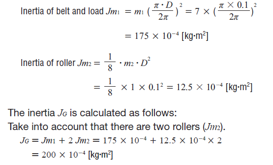
You’ll need to sum up the inertia values of all components driven by the motor, including the load, belt, and rollers. Two different equations will be used.
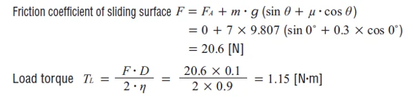
From what we’ve learned in [Motor Sizing Basics Part 1 – Load Torque], here’s the load torque calculation:
### Dealing with Large Load Inertia? Use a Geared Motor
If you’re dealing with high load inertia, there’s a simple way to reduce it exponentially. The load inertia is reduced by the square of the gear ratio. The resulting value is the **reflected load inertia**, which represents the load inertia at the motor shaft (instead of at the gearhead shaft).

If you’d like to learn more, here’s a white paper discussing how to use gearheads to reduce load inertia, specifically for stepper motors.
[White Paper: How to Address Increased Loads in Both Size and Weight with a Stepper Motor](http://bsg-i.nbxc.com/blog/70e8526c7dc0c5024343b13d64c85078.png)
### Where Can I Find Permissible Load Inertia?
After calculating your total load inertia, how do you find a motor that can handle it?
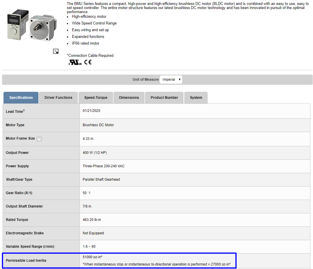
Here’s an example of a permissible load inertia chart for a BLE2 Series 200/400W brushless motor (from our catalog). Since we’ve already calculated the maximum permissible load inertia for each gear ratio, you don’t have to repeat the process. Try not to exceed these values. The motor may still work if these values are exceeded, but it cannot be guaranteed.
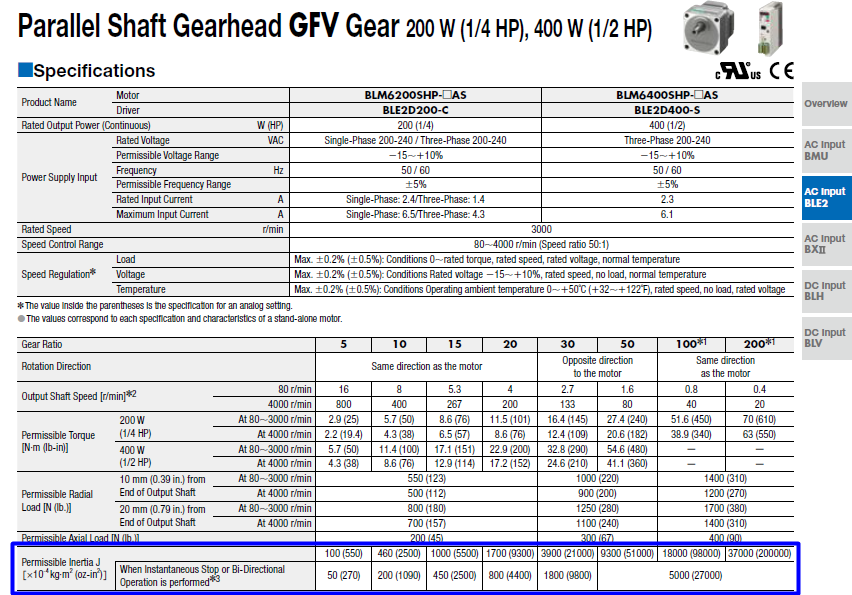
If you don’t have our catalog, we also list the permissible load inertia value on the website.
For stepper or servo motors, permissible load inertia values are not published, so please refer to recommended inertia ratio guidelines.
That’s it for load inertia for now. Remember that load inertia is just one of three critical calculations needed for successful motor sizing (don’t forget torque and speed). In the next Motor Sizing Basics post, I’ll explain how load inertia affects another component of torque—**acceleration torque**, which plays a crucial role in determining the total torque requirement for an application (and is why racing bikes feel easier to pedal than standard bikes).
Need a refresher? Here’s the motor sizing white paper (from the previous post).
[Learn more about motor sizing calculations](http://bsg-i.nbxc.com/blog/2202dc96d21c05a01f42902dad395e43.png)
In the next post, I’ll explain how to calculate acceleration torque, RMS torque, and speed.
[Motor Sizing Basics Part 3 – Acceleration Torque (and RMS Torque)](http://bsg-i.nbxc.com/blog/5596c5f4fef54d3ef2ebc36a56dd10bf.png)
Lastly, here’s the link to the previous post:
[Motor Sizing Basics Part 1 – Load Torque](http://bsg-i.nbxc.com/blog/d78acd0618bdd80deba13738852a399d.png)
**Tip**: Is there an easier way to size motors?
When it comes to motor sizing, accuracy is key. Ensure the data used for calculations is as precise as possible. The more assumptions you make, the larger the safety factor you’ll need at the end. After all, there will always be some unknowns in real-world applications.
Example: Belt Conveyor
[New Call-to-Action](http://bsg-i.nbxc.com/blog/c083023f139af2bc36579809ca3ddc2a.png)
[Try Our Motor Sizing Calculators](http://bsg-i.nbxc.com/blog/c083023f139af2bc36579809ca3ddc2a.png)
Medical Repair Injection Mould
Polyetheretherketone (PEEK) is a high-performance engineering plastic with excellent biocompatibility, biostability, high strength, rigidity and wear resistance. It also has high temperature tolerance, chemical stability and X-ray transparency, which makes PEEK widely used in the medical field, especially in orthopedic surgery.
Interface screw is a screw used to fix the interface connection between implanted devices and human tissues, usually used to provide stable implant positioning and support. In orthopedic surgery, interface screws are often used to fix bone parts after fractures or bone cutting, as well as soft tissue reconstruction and repair.
Peek interface screw die refers to the PEEK Suture Anchor mould to manufacture polyetheretherketone interface screws. The design of this plastic molds requires precise consideration of the shape, size, thread and other details of the screw to ensure that the produced screws can meet the strict requirements of medical implants.
The manufacture of injection mould usually includes multiple links such as design, processing, assembly and debugging. In the design stage, it is necessary to accurately calculate and design according to the specific requirements of the screw (such as size, shape, thread type, etc.); in the processing stage, high-precision machine tools and tools are needed for processing to ensure the accuracy and surface quality of the mold; finally, in the assembly and debugging stage, the plastic injection mold needs to be assembled and tested to ensure that it can normally produce qualified screws.
Due to the special properties of PEEK materials (such as high temperature tolerance, chemical stability, etc.), the manufacture of peek interface screw die needs to meet a series of technical requirements, such as high temperature resistance, corrosion resistance, high precision, etc. In addition, the material and manufacturing process of plastic molds also need to be strictly selected and controlled to ensure that they can meet the quality requirements of medical implants.
With the continuous advancement of medical technology and the continuous improvement of people's health needs, the requirements for implants in orthopedic surgery are also getting higher and higher. As a high-performance implant fixation device, polyetheretherketone interface screws play an increasingly important role in orthopedic surgery. Therefore, the manufacture and application of peek interface screw die also have broad market prospects and development space.
PEEK Suture Anchor mould,PEEK interface screw mould,PEEK Mould,PEEK interface screw die,peek interface screw die
Dongguan Hongke Plastic Precision Mould Co.,Limited , https://www.hongkemold.com