For those new to wiring I/O systems in motion control, the first time can feel daunting. If devices aren’t hooked up correctly, it can lead to anything from unexpected motor behavior to irreparable damage. Even after years of experience, I still get that nervous feeling just before pressing the start button on a demo. You know, Murphy’s Law!
The challenge often arises when engineers or manufacturers use different terminologies for wiring. How do you ensure you’re speaking the same language? For instance, is sourcing logic the same as PNP logic? Or are we “sinking†or “taking a sinked source� In our experience helping with motion control applications, we’ve encountered every variation of these questions.
Most of the time, technical support teams will point you toward a wiring diagram and tell you to follow it. But what exactly do sink logic and source logic mean? Let’s start with some foundational terms.
**Electronic Circuit (Digital)**
An electronic circuit comprises components like resistors, transistors, capacitors, inductors, and diodes. These are interconnected via conductive wires or traces on a printed circuit board (PCB). The circuit needs a voltage and ground, where the ground serves as a reference point for measuring potential voltage. A digital electronic circuit operates on DC voltage and uses discrete on/off values. A DC power source moves from positive to negative.
**I/O**
I/O stands for inputs/outputs, essentially anything that generates an output based on an input. Think of a keyboard (input) and a monitor (output). In this context, I/O refers to the signal communication between two devices, such as a programmable logic controller (PLC) and a stepper driver, using binary logic (on/off).
**Electrical Load**
An electrical load is a component or section of a circuit that consumes electric power. This contrasts with a power source, like a battery or generator, which generates power. Examples include light bulbs and motors. Here, we’re focusing on input circuits.
**Logic Circuit**
A logic circuit is an electric circuit (I/O) where the output depends on the input. It can have one or more binary inputs (on/off) and a single binary output. Components may include switches, relays, diodes, and transistors.
**Sink Logic vs Source Logic**
Sink and source logic circuits are often linked to PLC I/O signals and only apply to DC circuits. They differ based on the type of components used and how current flows.
- **Logic is defined by the type of components in the circuit.**
- **Logic determines current flow in the circuit.**
- **Whatever logic you use for the output, the opposite is needed for the input.**
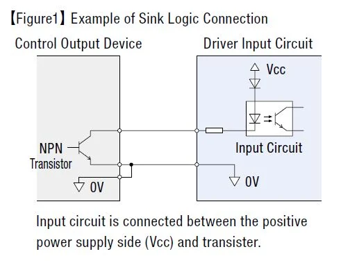
**Sink Logic**
In a sink logic setup, an NPN transistor creates a path to ground for the electrical load. An NPN transistor circuit works only when connected to a PNP transistor circuit. In other words, a sink logic circuit needs to be paired with a source logic circuit.
Figure 1 illustrates a sinking digital output connected to a sourcing digital input. The input circuit connects between the positive power supply (Vcc) and the NPN transistor.
**Source Logic**
For source logic, a PNP transistor provides a path to voltage for the electrical load. A PNP transistor circuit functions only when connected to an NPN transistor circuit. Hence, a source logic circuit requires pairing with a sink logic circuit.
Figure 2 shows a sourcing digital output connected to a sinking digital input. The input circuit links between the PNP transistor and the power supply ground (0V).
A useful mnemonic for distinguishing between sink and source logic is to think of a source logic circuit as the voltage source (providing a path to the source), while a sink logic circuit leads toward the ground (providing a path to ground).
**Tip: Compare Wiring Diagrams Side by Side**
When working with I/O wiring between a PLC and a servo or stepper driver, a helpful trick I’ve found effective is to print out the wiring diagrams from both the PLC and the driver, then place them side by side. This helps visualize the current flow from the voltage source to the load and back to the ground.
**Trace the Current Flow**
Many times, I’ve provided support remotely over the phone. This made wiring support particularly tricky. To avoid damaging customers’ PLCs, I used to print the wiring diagrams and trace the current flow from the voltage source, through the load, to the ground. Supporting remotely taught me how crucial it is to clearly understand which side of the I/O the customer is referring to.
To ensure a PLC sourcing output triggers a sinking input on the driver, confirm that everything has the required power. Sufficient voltage and current must enter the positive terminal from the PLC side, pass through the output circuit, reach the input circuit (the electrical load), and exit back to the ground of the power supply to complete the circuit. Each I/O signal on a PLC typically provides two terminals: one for incoming current and one for outgoing. Sometimes, to save space, terminals are grouped together and labeled “common.†This common terminal might be the voltage source or ground—more details below.
**Tip: Don’t Forget Power Requirements for I/O**
Pay attention to voltage and current requirements for both inputs and outputs. If the output requires current-limiting resistors, use Ohm’s Law to calculate external resistance, but don’t overlook internal resistance. Remember that meeting both voltage and current requirements of the input is essential.
**Which is Safer?**
It’s vital to consider the type of logic or transistor to determine the correct wiring method. There’s also a safety difference to keep in mind. If something happens to the customer’s device and causes an I/O signal line earth leakage or a short circuit of the ground (0V) line, it could pose risks.
However, using source logic prevents the input circuit from being directly connected to the positive power side (Vcc). Therefore, an earth leakage or short circuit of a signal line won’t activate the input. This makes source logic considered a safer connection method.
**Summary**
Sink and source are terms defining the flow of direct current in an electric circuit.
- A sinking input or output circuit provides a path to ground for the electric load.
- A sourcing input or output provides the voltage source for the electric load.
Logic is determined by the type of components in the circuit:
- A sourcing input or output circuit requires a PNP transistor.
- A sinking input or output circuit requires an NPN transistor.
A basic electronic circuit includes one digital input connected to a digital output. To power the circuit, you need a voltage source, a ground, and a load.
- A sourcing input or output circuit provides the necessary voltage for the circuit.
- A sinking input or output circuit provides the necessary ground for the circuit.
- The digital I/O provides the electrical load required for the circuit to function.
**For Flexibility, Use Products That Offer Both Sink and Source Logic**
Certain products in the market offer both sink and source logic for flexible connections. Bidirectional diodes wired in parallel enable this flexibility, and photo couplers reduce wiring damage risks. Choose these products if you need flexibility or plan to repurpose them later.
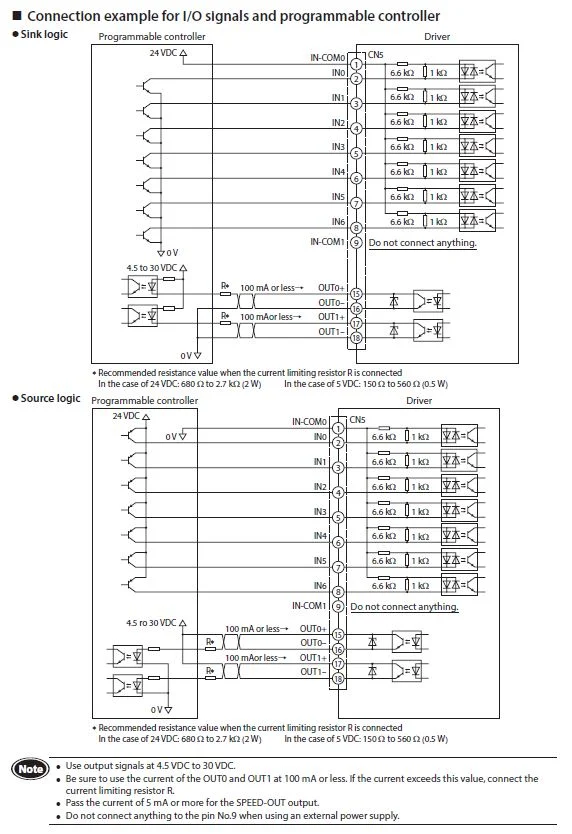
Here’s what the actual wiring diagrams look like for the BLE2 Series brushless motor drivers. There’s one diagram for connecting sink logic outputs and another for source logic outputs. The PLC is on the left, and the motor driver is on the right. The INx designations are inputs, and OUTx designations are outputs.
Take a look at the first input, "IN-COM0" (Inputs Common). On the top wiring diagram, it’s connected to 24VDC, and the input has a path to ground. On the bottom diagram, "IN-COM0" is connected to 0V, and the input has a path to the voltage source. The bidirectional diodes in the input circuits allow this.
Hopefully, this helps! Most of our newer drivers offer both sink and source logic. If you need help finding them, don’t hesitate to reach out to our helpful tech support engineers.
Thanks for reading this far and please subscribe!
Mobility Scooter
Mobility Scooter,Mobility Scooter For Elderly,Electric Mibility Scooter,Disabled Mobility Scooters
YUMBOMOBILITY LTD , https://www.yumbomobility.com